|
|
|
Brian Davies
rx7@zeroglabs.com
1.0
Introduction
This
information is meant to help others trying to convert their power steering
equipped RX-7 to a system using a power steering rack, but no assist from
a pump. This will allow
you to remove your pump, belt, pulley, cooling loop, etc from the car. I
am NOT any sort of expert on this matter, so follow my advice at your own
risk. I will say that
I have completed this modification on my own car and it works great for
me.
Important: I
made my modifications when the engine was removed from the car so I had
easy access to the steering rack without removing it. Since
you will probably not have your engine out, I think you need to remove
the steering rack from the car to gain access to all the bolts and fittings. Maybe
not
. Im not sure
but Id imagine that youll run into clearance problems
for wrenches if you dont pull the rack from the car.
2.0
What to expect when youre finished/FAQ
Probably
the question that youre most eager to know the answer to is How hard
will my car be to steer when I am done?. Just
so you know, I have 225/50 R16 Toyo Proxes RA-1 tires on my car (This model
of tire is particularly sticky). Here
are my thoughts on steering effort:
Dead
Stop
Wheel
takes quite a bit of effort to turn. Definitely
not easy, but you can do it if you just put a little muscle into it. Not
recommended if you have a wife or girlfriend that isnt too strong! :)
Slowly
Rolling (less than 5 mph)
Still
very firm feel to the wheel and still feels pretty heavy.
Slowly
Driving (around 15 mph)
Wheel
feels like it has some weight to it, but can be turned with one hand as
long as you have a good grip and are not some kinda wimp. :)
Right hand turns are the only time where you think Gee, this is kinda
heavy!.
Driving
(25 mph and up)
Feels
great! Doesnt really
feel much heavier than it did before you take off the P/S pump.
3.0
How I THINK the P/S rack works
The
P/S pump supplies high pressure fluid to 2 hoses that are connected down
to the rack near the pinion.I have
marked these in red in the diagram below.
Now,
built into the pinion area is a 'mystery valve'. I
don't really know what it looks like, but let's just say that when you
turn the steering wheel, it moves the valve and makes stuff happen.
Now,
also built into the pinion area are 2 metal lines coming out. Each
metal line goes over to a different position on the long part of the rack. One
goes to one end and one goes to kinda in the middle.
What
happens is that as you turn the wheel, the mystery valve can distribute
pressure from the 2 incoming high pressure hoses from the pump to the 2
metal tubes going to the two different spots on the rack. I
have colored these in orange.
Now,
INSIDE the rack is some sort of partition or seal. When
one of the 2 metal lines (orange colored) is supplying more pressure than
the other, it causes unequal pressure on the two sides of the seal. The
rack moves and your wheels turn. That
is where the "assist" comes from. Don't
forget, that even with none of the fluid doing anything, the pinion is
still in direct physical contact with the rack, so that is helping a bit
too and controlling the motion of the rack....
Now, just
to throw one more thing in, there is an output from the pinion area that
goes to a loop of metal tubing mounted in front of the radiator... then
it goes back and dumps fluid into the pump again. This
loop is to cool your P/S fluid, as it can get quite hot due to the pump
working on it. I have
colored this blue in the picture.
4.0
Problems and Solutions
Now,
when you want to remove your P/S pump, you are faced with a couple of problems
that you need to fix.....
4.1
The Problems
1)
you need to make sure that pressure is allowed to equalize all the time
from one side of the partition to the other. Otherwise
it may bind up... that would be annoying and potentially very dangerous.
2)
you need to find a way to plug up the places that will now be 'empty' on
your rack once you start removing all these lines....
4.2
My Solutions
These
arent the most professional solutions, but they work for me!
4.2.1
Equalize Pressures
To
make sure pressure is equal on both sides, remove both metal tubes (orange
in my picture). Dont
throw them away though, youll need the fittings. You
will be connecting the two fittings on the rack together and plugging the
two fittings on the steering gear.
Then
go to the hardware store and get these items:
One
1/4 inch Tube Union with inserts.-
Straight type
One
1/4 inch Tube Union with inserts.-
90 degree angle type
About
one foot of 1/4 inch copper tubing (you wont use it all, but getting a
bit extra is a good idea)
NOTE: In case
youre wondering about my tube unions
I got them at Home Depot. They
are made by a company called Anderson Barrows and are sold in little
plastic baggies. The
barcode info on the straight type is 0-48643-07036-3. Sorry,
but I dont have barcode info for the 90 degree bent ones.
Now,
take your two metal tubes (orange in my picture) and cut off the ends with
a tubing cutter. So you
will end up with 4 chopped off end pieces. When
you do this, leave as much of the straight part of the original end as
possible. The reason
for this will become clear in a minute. Check
out this picture for help:
Now, using
your nifty tubing unions, the copper tubing, and the two ends that you
got from the factory tubes, make a little piece to join the two parts of
the rack. This is why
you wanted to leave as much of the straight part as possible. Then
install it to connect the two parts of the rack. Putting
the bend in it is good for two reasons. First,
it helps it stay tucked away under the oil pan and nicely bends around
the steering rack mount area and doesnt hit on anything. Second,
you want to purposely make it JUST a bit extra curved and JUST a tiny bit
too short. The reason
for this is that when you put it in you kinda need to have just a bit of
flex in it to simultaneously plug it into two holes at one time. The
bend give you a little extra length on reserve if you need it. Here
is a drawing kinda like the one I made. I
could not get an actual picture because it is too hard to see:
I
hope you see what I mean about having some extra bendiness in the thing
.
Imagine trying to insert the above into BOTH fittings at once. Youd
have trouble if you didnt have a little extra flex and length stored
in the bend.
4.2.2
Plug those holes!
So,
now you can remove your pump, the high pressure lines, and the cooling
loop.
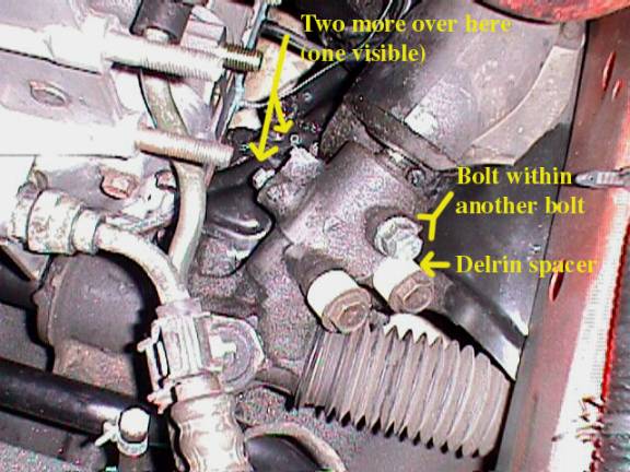
OK,
you will have 2 large banjo fittings that are now 'blank' (no banjo part)
because you've removed the 2 high pressure lines from the pump. These
are red in the diagram.
I
made two spacers out of Delrin (a type of plastic that you can buy; usually
sold as long rods) on a lathe that looked just like the banjo part, but
with no outlet where the hose would normally attach. This
was cheaper and faster than finding huge bolts and then matching threads
and sawing them down, etc
The
outlet going to the cooling loop is now blank. There
should be a hose with a fitting on the end, but now, it's just open. This
is blue in the picture.
You
COULD buy a big huge bolt to go in there, but these aren't easy to find
(near me anyway). Since
I was not planning on ever trying to 'undo' my conversion, I sawed the
hose in half so that I could get the bolt/fitting. Of
course, that has a big hole in the middle for the hose that used to go
there. So I tapped the
inside of the bolt/fitting
with
a dirt-common size american thread and then bought a small bolt (sawed
it down to fit) and put it inside the original one with some sealant. Remember,
dont let the new assembly protrude into the steering gear area any farther
than it came from the factory, or it may catch on something. Then
I put it into the hole. Hey,
not too professional... but it doesn't leak and is cheap if you already
own a tap and die set!
You
will also have 2 holes where the metal tubes used to come out of the steering
gear area and go to the rack. These
were orange in the picture. You
can do the same trick as before
. Use your chopped off ends from the steps
above. Then tap out the
center with whatever common bolt size and thread you like and plug the
center with a bolt. Then
install the whole mess into the pinion. Remember,
dont let the new assembly protrude into the steering gear area any farther
than it came from the factory, or it may catch on something.
Check
out this picture for what my steering gear area now looks like:
4.3
A few last things
OK,
now after youve gotten everything squared away, you need to test this
out with the front of the car jacked up. Once
the front end of the car is up in the air, insert your key and carefully
turn the key JUST far enough to unlock the steering wheel. Now,
move the wheel from lock to lock a few times
. Go slowly at first to make
sure nothing is binding or catching. Then
go faster to make sure everything is smooth. You
shouldnt feel anything sticking or catching.
Safety
is important!Make SURE you can steer
the car OK BEFORE you go on the road!
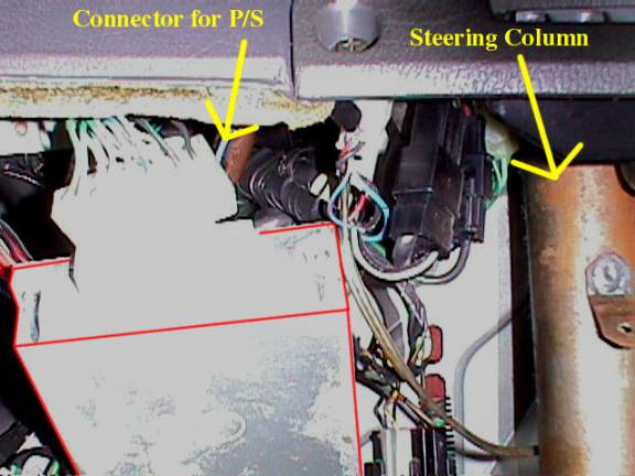
You
may notice some beeping noises coming from under your dash now that your
P/S system is gone. This
is the power steering control units way of saying that it thinks the pump
is broken. Just unplug
the connector and it will be silenced. Here
is a picture of the area under the steering wheel. I
got a lot of glare from the flash on the camera, so I outlined the shape
of the box in red
sorry! The
power steering control unit is the large silver box.