Would you like to make this site your homepage? It's fast and easy...
Yes, Please make this my home page!
Fixing The Main Wiper Switch
INTRODUCTION
This document describes how to fix the wiper switch. I have done it on my '87 RX-7 (turbo, tilted steering wheel) and
it cured the problem. The symptoms were that the windshield wiper works
only in LO speed but not in INT and HI positions. This document describes
how I performed the fix based on directions posted by several people in
the FC3S list.
It is up to you to decide if this fix is appropriate to your case.
FORWARD
The wiper switch controls the main windshield wipers as well as controls
the rear window wiper, misters, and hazard lights. The wiper switch seems
to have a problem common to many 2nd gen. RX-7's. In my case, the main
windshield wiper did not work in the HI and INT but works just fine in
the LO setting. New wiper switch units are available from Mazda dealers
and Mazdatrix; but
due to their high cost (over $200) some RX-7 owners might choose to fix
them instead. The problem in my case, as pointed out by people on the FC3S
list, was bad contacts in one of the relays. The FC3S
FAQ suggests to clean the relay switches;
however some individuals on the list mentioned that this fix is only temporary.
In so being, I decided to replace the damaged relay with a new one. The
relay I used, as suggested by Mike Gordon, is G6C-2114-US-DC12 made
by Omron Electronics Inc.
This is a 12V, PCB relay, 8A SPST-NO/SPST-NC which is a drop-in replacement
and its pin-out is identical to that of the original relay. A good source
for the relay is Digi-Key
(1-800-344-4539) which carries this relay as item Z950-ND. It can be ordered
using Digi-Key's on-line
ordering system and it costs
$6.24 plus a $5 penalty for small orders plus the actual shipping cost.
The main difficulty in performing this fix is to access and remove the
old relay. The FC3S FAQ
suggests to remove the wiper switch printed circuit board (PCB) by de-soldering
it. Another approach which was suggested on the FC3S list is to cut, using
a Dremel
tool an opening in the wiper switch cover; this is the method which is
described in this document.
The rest of this document describes how to replace the faulty relay
with the new one. It also contains a sections which describes how to verify
that the relay in your wiper switch is indeed bad.
REMOVING THE WIPER SWITCH AND ITS COVER
Removing the wiper switch and its back cover are done in the steps
outlined below. When done, you will end up with the 'naked' wiper switch
as shown in Figure 1.
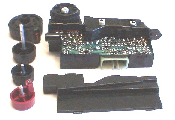 Figure 1 - The wiper switch taken apart.
Note that the instruction below are for an FC3S with tilted steering
wheel which might make the removal of the wiper switch easier. If your
car does not have a tilted steering wheel, follow the instruction in the
Shop Manual to remove the unit.
-
Disconnect the NEGATIVE battery cable (with negative ground cars like our
FC3S, always disconnect the negative cable first and connect it last, this
reduces the risk of causing short circuit by touching the car body with
the wrench).
Note: the switches should be plugged in and out only when the
battery is disconnected and the ignition switch is off. We will not mention
it again in the rest of the document so it is your responsibility to remember
that.
-
Remove the cluster switch panel (the unit that contains the wiper, signal,
light, and cruise control switches). Note that the cluster switch panel
is held in place by five screws (2 at the bottom and 3 near the instrument
panel) and is connected by four (in my FC3S which has cruise control) electrical
connectors (two at the right and two at the left).
-
Remove the wiper switch buttons. This is done by holding them firmly and
pulling them away. You may also push them with a screwdriver from the inside
of the cluster switch panel while you pull them away.
-
Remove the wiper switch. It is held in place by two screws. In my case,
I had to remove also the cruise control switch to clear the way for the
wiper switch.
-
Remove the wiper switch cover, this is done by prying on it with a screwdriver.
Be careful not to damage electronic parts under the cover. The cover does
not seem to break easily and even if it is breaks, it is not a big problem
as you can glue it back without affecting the performance of the switch.
If everything went OK, you will end up with the parts as shown above
in Figure 1.
CHECKING THE RELAY
Before you replace the relay, you might want to make sure this is indeed
the cause of the problem. First you need to identify the relay. The wiper
switch has three relays: Relay 1, Relay 2, and Relay 3. The three relays
are mounted on the component side of the PCB. Relay 1 is fully exposed,
Relay 2 is partially exposed, and Relay 3 is fully covered. Figure
3 shows the three relays after exposing relay 3 (more about it later).
Relay 3, which is the one we are going to replace, is shown on the
lower right corner in Figure 3 (this
relay is the bottom relay when the WSC is installed in the car).
Now we need to identify the six pins of Relay 3 on the back side of
the PCB. The six pins, which are directly below Relay 3 has the following
pin out diagram:
 Figure 2 - Relay 3 pin out (bottom view).
Contacts are shown in the normal (rest) position.
Figure 2 - Relay 3 pin out (bottom view).
Contacts are shown in the normal (rest) position.
Before we start with the check, note that this is a brief check that
tests only for the common symptoms of malfunction, that is, that one of
the switches of the relay does not connect when it should. It is also assumed
that you are using a digital voltmeter with automatic polarity setting.
If not, no problem, if the voltage you measure is negative, exchange the
position of the two probes.
Relay 3 contact check:
-
With the battery disconnected, connect the wiper switch to the car (we
don't need the other switches at this point).
-
Make sure nothing is going to short circuit, and then connect the battery
and turn the ignition switch to the ON position.
-
Set the speed to LO and make sure the voltage between the pins of the relay
coils are close to zero VDC.
-
Measure the voltage across the normally closed contacts of the relay (upper
left corner in Figure 2). It should be
zero VDC since the relay is not activated.
-
Set the speed to HI and make sure the voltage between the pins of the relay
coils are about 12VDC.
-
Measure the voltage across the normally open contacts of the relay (lower
left corner in Figure 2). It should be
zero VDC since the relay is activated.
If one of the switches has 12VDC across it while it should be closed,
the switch seems to fail and replacing the relay is likely to fix the problem.
Otherwise, further investigation which is outside the scope of this document
is required. In my case, the normally open switch failed to close.
REMOVING THE RELAY
To remove Relay 3 you need to access the relay from both sides
of the PCB. The removal of the switch cover done earlier has exposed the
PCB side of the relay. Now we will need to expose it from the component
side. Figure 2 and Figure
3 (a close-up) show the component side of the wiper switch with the
relay exposed. Using a Dremel tool carefully cut the cover until Relay
3 is fully exposed.
 Figure 3- The three relays from left to right are Relay 1, Relay
2, and Relay 3.
Relay 3 (right) being the one we are going to replace and is
is exposed from
the component side by cutting the switch surface.
Figure 3- The three relays from left to right are Relay 1, Relay
2, and Relay 3.
Relay 3 (right) being the one we are going to replace and is
is exposed from
the component side by cutting the switch surface.
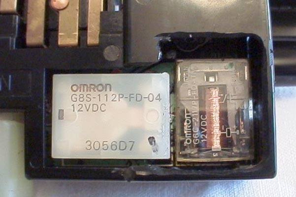 Figure 4 - close up of the exposed Relay 3 (vertical, on the right
hand)
Figure 4 - close up of the exposed Relay 3 (vertical, on the right
hand)
After exposing the relay, remove it by de-soldering its six pins shown
in Figure 5, and puling it out. It is
hard to pull the relay out intact but don't worry if you damage or break
it, as we are going to replace it anyway. Be careful however not to damage
the PCB or other parts of the switch. I found that it is easier to remove
the relay if you can access it with a screw driver from the side, between
its base and the PCB. For that reason, I made an extra hole on the right
side (using the orientation in figure 3) of the switch as shown in Figure
5.
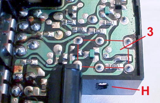 Figure 5 - the bottom side of Relay 3. Note also see leverage access
hole marked 'H'.
Figure 5 - the bottom side of Relay 3. Note also see leverage access
hole marked 'H'.
If every thing went OK, the PCB at the vacant location of the relay
will look as in Figure 6. Make sure
to clean any excess solder that can shorten between PCB traces.
 Figure 6 - A close-up of the vacant location of the Relay
3.
Figure 6 - A close-up of the vacant location of the Relay
3.
INSTALLING THE NEW RELAY
To install the new relay in place of Relay 3, simply make sure that
the PCB and the six holes of the relay pads are clean (look for short circuits
on the component side under the relay, after installing the relay, you
will have not access to clean it), insert the relay and solder it carefully.
Note that because of the asymmetric spacing between the relay pads,
it fits in only in the correct orientation. The installed relay is shown
in Figure 7.
 Figure 7 - The new relay installed in the vacant location
of the Relay 3.
TESTING THE SWITCH
Figure 7 - The new relay installed in the vacant location
of the Relay 3.
TESTING THE SWITCH
To test the switch you don't have to install the entire cluster switch
panel. You can simply connect only the wiper switch itself, and test it
separately. Make sure that when you connect or disconnect the wiper switch,
the battery is disconnected and the ignition switch is in the OFF position.
NOTE ON THE SWITCH LIGHTS
When the cluster switch panel is removed, it is a good time to replace
burnt bulbs in all the cluster switch panel unit. In my case, one of the
bulbs of the wiper switch (the one that is missing in Figure
3) did not work. I could not find an original replacement part, so
instead I used Radio Shack
272-1092 micro lamps (12v, 60 ma, 2 per $1.49) and installed it onto the
base of the original lamp. Really easy. Mike
Gordon suggests to use two of the above bulbs to match the power rating
of the original lamp.
INSTALLATION
If the wiper switch and the lights work OK, install everything is reverse
order, reconnect the battery and make sure all the switches of the cluster
switch panel work properly.